

The inspection methods, procedures and precautions for bulldozers
The bulldozer is the core equipment for precise earth leveling operations. Its value lies in the ability to achieve millimeter-level leveling accuracy through the use of six-direction adjustable tines. Unlike the powerful earth-moving operation of a bulldozer, the core of the inspection for a grading machine lies in "precision calibration" - the cumulative errors of the rotation disc gap, the hinge gap, and the guide gap of the bucket. These will directly translate into deviations in the road's flatness. The following elaborates on the key inspection points from five major dimensions: the rotation disc and traction frame system, the hinge and frame system, the bucket assembly, the automatic leveling control system, and the movement and hydraulic systems.
I. Deep Inspection of the Rotating Disc and Traction Frame System - The "Heart" of the Excavator's Accuracy
The rotating disc (rotation circle) and the traction frame are the most crucial components that distinguish the excavator from other earthmoving machinery. The gap between them is the primary indicator of the overall accuracy capability of the entire machine.
Precise measurement of the gap between the turntable
Measurement tools: Micrometer / Dial Indicator and Magnetic Indicator Stand.
Radial clearance measurement: Attach the dial indicator base to the traction frame, with the indicator head vertically touching the outer edge of the gear ring of the rotating disc (or the side of the chisel installation seat). Operate the side extension oil cylinder of the chisel, apply a gentle load to one side, and read the maximum deflection of the dial indicator, which is the radial clearance.
Axial clearance measurement: Place the dial head vertically against the upper plane of the rotating disc (or the end face of the gear ring). Operate the lifting cylinder of the chisel to make the chisel lightly touch the ground and apply an upward force. Read the maximum deflection of the dial indicator, which is the axial clearance.
Judgment criteria: Both radial and axial clearances should be within the range specified by the manufacturer (typically radial ≤ 1-2mm, axial ≤ 0.5-1.5mm, depending on the size of the machine). If they exceed the standard values, it indicates that the wear-resistant copper sleeve or liner of the turntable has been severely worn, and repair requires disassembling the entire traction frame assembly, which is extremely costly.
Diagnosis of rotation abnormal noise: During the rotation dynamic test, listen closely to the turntable throughout the process. Periodic "clicking" sounds indicate damage to the gear ring or the tooth surface of the worm gear reducer; continuous "squeaking" friction sounds suggest the detachment of the sealing belt or the drying out of the lubricating grease.
Accumulation of gap at the connection points of the traction frame
The connection ball head or pin of the traction frame (Type A frame or parallelogram linkage) with the front frame should be measured for clearance using a feeler gauge or a micrometer. If the clearance is too large at this point, it will cause the shovel blade to move back and forth, directly affecting the flatness accuracy.
Inspection of copper sleeves/sleeves at the hinge points of the traction frame's connecting rods - Use a lever to move the connecting rod and feel the gap. The cumulative gap at all hinge points will ultimately manifest as jitter and positioning errors during the shovel operation.
Turntable drive mechanism
The hydraulic motor/twin-gear reducer housing shows no oil leakage, and the rotation movement is smooth and continuous throughout the entire cycle without any jamming.
The torque of the connecting bolts between the turntable and the traction frame is randomly inspected. Any looseness will cause the turntable to sway.
II. In-depth Inspection of Hinge and Frame System - Ensuring Driving Accuracy and Structural Integrity
The scraper adopts a front and rear frame hinge structure, and the hinge points are one of the areas where the entire machine experiences the most concentrated force.
Quantitative measurement of the hinge joint gap
Measurement method: Attach the dial indicator base to the front or rear frame. The indicator head should be in contact with the end face of the articulated pin shaft (for measuring axial clearance) or the outer circle of the pin shaft (for measuring radial clearance). Rotate the articulated joint and read the deflection of the dial indicator when applying slight loads to the left and right directions.
Judgment criteria: The hinge clearance should be within the range specified by the manufacturer. Exceeding the clearance will cause the rear frame to "sway" (zigzag) during driving, and the bucket will be unable to maintain a straight working trajectory.
Hinged bearing seat: Use a strong flashlight to check for any cracks in the welds of the hinged seat. The dust-proof sealing ring at the hinge joint is in good condition - failure of the seal allows dust to enter, which is the main reason for the accelerated wear of the hinge gap.
Straightness of the front and rear frames and weld inspection
On a flat surface, visually inspect from a distance whether the front and rear frames are aligned on the same longitudinal axis. Permanent deviations of the hinge points due to overload or collision will result in a systematic deviation between the bucket and the actual ground when it is in a horizontal position.
Key weld seams of the front frame: Welding area of the shovel traction frame mounting support, front axle swing fork mounting support, and hinged seat.
The key weld seams of the rear frame: the hinged seat, the transmission support beam, the connection area of the rear axle housing, and the installation seat of the soil loosener.
III. Inspection of the total assembly of the shovel and the depth of six-directional movement
Quantification of the wear of the shovel body
Use an ultrasonic thickness gauge to measure the grid points at the cutting edge area of the blade, and record the minimum wall thickness. The reduction of the bottom wall thickness will result in the loss of bending stiffness, and cause elastic deformation when scraping the hard surface, thereby affecting the flatness.
Chisel blade/blade - The remaining edge height should be measured multiple times using a caliper. Uneven wear of the blade (thicker at one end and thinner at the other) indicates that the chisel has been subjected to long-term uneven loading or there is a problem with the operation method. It is necessary to record this and advise the user to adjust the working method.
Verification of the full range of motion for the shovel's six-directional operation
The blade of the bulldozer has six-directional adjustment capabilities. During the inspection, each action must be performed for at least two full strokes.
Lifting (left and right independently or simultaneously): The entire travel is smooth without any crawling. Check for synchronization between left and right - the height difference between the two ends of the shovel blade should be within the allowable range.
Tilt (left-right tilt): The full-angle tilting action is smooth, and there is no leakage in the cylinders.
Rotation (rotation around the vertical axis): The shovel rotates 360° (as permitted by the design), and the turntable makes no abnormal noise or jamming.
Side extension (the shovel is moved horizontally to the left or right): The entire movement is smooth. The gap between the guide slider/track is measured using a feeler gauge.
Pitch (adjusting the cutting angle of the shovel): The pitch cylinder operates normally, and the range of the shovel's inclination from front to back meets the standards.
Swing angle (adjusting the lateral movement of the blade within the horizontal plane): The swing angle cylinder or mechanical adjustment mechanism functions properly and is securely locked.
Cumulative inspection of the gap between the shovel blade and the guide plate
The sliding rail/ mounting base that connects the shovel blade to the turntable is worn out, as well as the clearance between the guide slider of the side extension cylinder. These together form the clearance for guiding the shovel blade. By using a feeler gauge to measure point by point, if the cumulative gap is too large, it will cause the shovel blade to deviate when under heavy load and unable to maintain the set angle.
IV. In-depth Inspection of Automatic Leveling and Control System - The "Brain" of High-End Grader Machines
For graders equipped with an automatic leveling system, the inspection of their electrical control system is of utmost importance.
System self-check and sensor status
The controller passed the power-on self-check and there were no fault codes. All parameters on the display were displayed normally.
Longitudinal leveling sensor: Ultrasonic type - probe surface is clean, without mud or dirt coverage, and cable connection is tight. Mechanical sliding shoe type - check the wear of the sliding shoe bottom surface, and the swing arm rotates flexibly. Laser receiver type - the receiving window is clean, and the mast is not deformed.
Slope sensor: Installed securely, self-test passed. Place the scraper on a known horizontal surface. The slope display reading should be consistent with the actual value.
Baseline/Raise Beam (for wire rope leveling): Sensitivity test of the sensor to track the baseline - Manually slightly move the sensor arm, and the control system should respond promptly to adjust the lifting and lowering of the shovel.
Verification of automatic control function
Set a certain blade elevation or slope value, then switch to the automatic mode.
Manually change the load on the shovel (such as gently pushing the shovel to the ground and applying pressure), and observe whether the system automatically adjusts the shovel's elevation to restore the set value.
Response speed and stability are the key factors in evaluating the performance of an automatic leveling system - too slow a response leads to lag in leveling, while too fast a response results in excessive correction and the generation of waves.
Common causes of system failure
The sensor cable is damaged (due to collision during construction or aging).
The valve core of the hydraulic proportional valve is stuck (the main cause is the unqualified cleanliness of the hydraulic oil).
Internal failure of the controller (due to poor heat dissipation or water ingress).
V. Deep Inspection of the Walking and Hydraulic Systems
Diagnosis of the cause of the vehicle's swaying during driving
Driving at high speed in a straight line on a flat road, gently hold the steering wheel with both hands, and observe whether the vehicle automatically veers off course or takes on a serpentine motion.
The sequence for troubleshooting the cause of snake-like movement: excessive hinge clearance → loosening of the rear axle steering link → uneven tire pressure → inaccurate front axle alignment. The inspection report should record the degree of snake-like movement and the possible causes.
Front axle oscillation system and tire uneven wear
Measurement of the clearance between the swing pin of the front axle and the pinion of the balance box. If this clearance is too large, it will cause inaccurate front wheel alignment, resulting in severe tire wear.
Observe whether there are any unilateral wear steps on the tire tread - this is an "external sign" indicating a problem with the front axle swing system or an incorrect front wheel alignment.
Hydraulic system pressure maintenance and pressure test
Pneumatic cylinder for lifting the shovel test for pressure retention - Raise the shovel to its highest position, turn off the engine, mark the position of the piston rod, and leave it stationary for 10 minutes. If the descent amount exceeds the standard, it indicates that there is internal leakage in the cylinder or leakage in the directional control valve.
The overflow pressures of each working circuit are measured using pressure gauge sets and compared with the manufacturer's standards.
Rear axle balance box and series drive
The oil level check of the rear axle balance box (such as the dual-axle rear axle) shows that the oscillation function is normal. The balance box is a key component for the rear axle of the utility vehicle to adapt to uneven terrain. Its malfunction will affect the uniformity of tire contact with the ground and the smoothness of the vehicle's operation.
VI. Special Inspection Points
Cab ROPS/FOPS Structure
The cab of a bulldozer usually incorporates a roll prevention/obstacle protection structure. The pillars have no bending or deformation, the top has no depression, and the welding points have no cracks. Any structural damage is considered non-compliant.
Oil analysis - Hydraulic cleanliness is the key point
It is strongly recommended to collect the hydraulic oil sample and send it to the laboratory for testing of the cleanliness level (according to ISO 4406). The hydraulic system of the scraper excavator contains precise automatic leveling proportional valves, which are extremely sensitive to the cleanliness of the oil. Exceeding the cleanliness standard may cause the proportional valve to get stuck and the automatic leveling function to fail.
Safety during the rotation of the shovel
When the shovel rotates, the areas swept by both ends of the shovel are quite large. Inspectors must stand at a safe distance. It is strictly prohibited for anyone to stay within the radius of the shovel's rotation.
Key points for photo archives
The PIN code and the entire machine's nameplate are independently archived.
Measurement process of the turntable gap - Close-up of the installation and reading of the dial indicator (one for the radial direction and one for the axial direction).
Photo of the gap measurement of the articulated pin shaft.
The thickness measurement reading of the bottom of the shovel is displayed in the same frame as the measurement location.
The screen display of the automatic leveling system controller (the self-check passed screen).
Close-up of uneven tire wear.
Photo of the front axle swing pinion shaft area.
分享这个商品
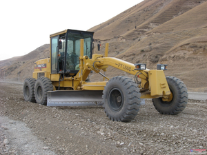
The inspection methods, procedures and precautions for bulldozers
The bulldozer is the core equipment for precise earth leveling operations. Its value lies in the ability to achieve millimeter-level leveling accuracy through the use of six-direction adjustable tines.