

Inspection methods, procedures and precautions for rotary tillers
The rotary tiller is a drive-type tillage and soil preparation machine that is used in conjunction with a tractor. It is driven by the power output shaft (PTO) of the tractor to rotate the blade shaft at high speed, completing multiple processes such as plowing, soil crushing, and leveling in a single operation. It is widely used for pre-planting soil preparation in paddy fields, dry land, orchards, and vegetable fields, and is one of the most commonly used agricultural machinery in agricultural production. Due to the heavy workload and harsh operating environment (such as sandy soil, crop residues, and field moisture), faults such as blade wear, damage to the blade shaft bearings, oil leakage in the gearbox, and breakage of the universal joint frequently occur. Moreover, if the blade breaks and flies out, it can cause serious personal injury. In scenarios such as new machine delivery and acceptance, verification of agricultural subsidies, second-hand transactions, inspection of equipment for cross-regional operation teams, and pre-tilting inspection before the farming season, a comprehensive system inspection covering the blade shaft, transmission system, safety protection, and tillage quality is a basic requirement for ensuring farming efficiency and the personal safety of operators.
I. Overview of Inspection Methods
Based on the attachment type of the rotary tiller (悬挂式/Traction type), the layout of the blade shaft (horizontal/vertical), the width of the plowing area, the type of blades (curved blades/chevron-shaped blades/rectangular blades) and the requirements of the client, the inspection comprehensively employs the following methods
Static full inspection: The rotary tiller is left to stand still. Each component such as the frame, suspension frame, gearbox, blade shaft assembly, blade, side plate, drag plate/pressing roller, universal joint transmission shaft, and safety guard cover is inspected item by item, touched by hand, and measured with measuring tools.
Dynamic operation test: After coupling with the tractor, start the PTO on a safe area, verify the rotation of the cutter shaft, the operation of the gearbox, and the vibration conditions. Listen for any abnormal sounds or abnormal temperature rise.
Trial farming verification (as needed): Conduct short-distance trial farming on fields where conditions permit. Measure core operation indicators such as plowing depth, plowing depth stability, soil fragmentation rate, and vegetation coverage. Comprehensive evaluation of the overall farming quality of the machine is carried out.
Document and label traceability: Verify the consistency between the entire machine label, the gearbox label and the certificate of conformity, as well as the promotion and certification documents (if subsidies are involved).
The third-party inspection is carried out based on the "static full inspection + dynamic operation test + functional verification" package. When conducting the verification of agricultural machinery subsidies, it is necessary to additionally check the consistency between the promotion and certification certificate and the machine number.
II. Inspection Process
1. Data Collection and Preparation for Inspection
The client provides a list of the machines to be inspected, specifying the manufacturer, model, range of power supply, width of plowing, rotational speed of the blade shaft (corresponding to the PTO speed), type and quantity of blades, connection method, factory serial number, applicable standards (such as GB/T 5668, JB/T 9798, etc.). The inspector prepares: tape measure, vernier caliper, steel ruler, level gauge, speedometer, infrared thermometer, soil hardness tester, plowing depth measuring ruler, etc.
2. Confirmation of Venue and Safety Conditions
Static inspection is conducted on a hard and flat surface. Dynamic testing must be carried out on a safe open area. After the tiller is attached, no one is allowed to stand below or behind the blade shaft. The test ploughing should be carried out in representative fields, and there should be no obstacles within the operation area. Inspectors should wear safety helmets, anti-shatter shoes, and tight work clothes. When inspecting or replacing the blade, it is necessary to confirm that the tractor has been turned off, the PTO has been disconnected, and the blade shaft has completely stopped.
3. Identity and Label Verification
Machine nameplate: Verify the manufacturer, model, factory serial number, manufacturing date, swath width, matching power, spindle speed, etc.
Gearbox nameplate: Verify the model and gear ratio, and confirm the compatibility with the entire machine.
Promotion certification (subsidy verification): Verify the model, enterprise, and validity period.
4. Inspection of the frame and suspension system
Frame: The main beam, side plates, and suspension frame show no deformation or weld cracks. The side plates (the support plates for the cutter shaft on both the left and right sides) are the key structure that bears the radial force of the cutter shaft. The focus of inspection is on whether there are any cracks in the welding area between the side plates and the main beam.
Suspension frame: The three-point suspension pin holes show no severe wear (elliptical deformation), and the pin hole dimensions match those of the tractor coupling pin. The suspension frame is not deformed.
Frame level: Place the tiller on a flat surface and use a level gauge to check the lateral levelness of the frame. Frame distortion will result in inconsistent tillage depths on the left and right sides.
5. Inspection of the knife shaft and blade assembly - Core working component
Blade shaft
Appearance of the knife shaft: The tube body of the knife shaft shows no deformation, no cracks, and no signs of welding repair. The installation positions of the bearings at both ends of the knife shaft show no wear or looseness.
Tool holder (tool magazine): The tool holder is welded onto the tool shaft and is used to fix the tool blades. Check one by one whether there are any cracks in the welds of the tool holder - cracks in the tool holder can cause it to fly off during high-speed rotation, which is a serious safety hazard. The tool holder shows no deformation or fracture.
Blade shaft dynamic balance: The blade shaft undergoes dynamic balance testing upon leaving the factory. If there are missing, broken blades or the blade seat falls off and is re-welded, the dynamic balance of the blade shaft is disrupted, resulting in severe vibration during operation. The degree of vibration felt by the frame during dynamic testing is the method for judgment.
Blade
Blade wear: The scythe is the most common type of knife. The blade (side edge and straight edge) should be sharp. Use a caliper to measure the thickness of the edge - new ones are usually 0.5-1mm, and an edge thickness exceeding 2mm indicates a dull knife, significantly increasing the working resistance. A larger radius of the blade tip arc will also affect the ability to penetrate the soil.
Blade damage: Check each blade for cracks - especially at the bend of the handle and at the root of the cutting edge, as these are stress concentration points. Any blade with cracks must be replaced immediately. Severely deformed blades (bent, twisted) also need to be replaced.
Missing blades: Count the number of missing blades. Missing blades not only result in a decline in farming quality (due to missed plowing), but also disrupt the dynamic balance of the blade shaft.
Blade installation direction: The curved blades can be either left-curving or right-curving. They are arranged alternately on the blade shaft in a spiral pattern. The inspector should confirm that the blade installation direction is correct - the cutting edge faces the direction of rotation, and the left and right curved blades are arranged alternately, without any single-sided concentrated arrangement.
Blade fastening bolts: Check the tightening status of each blade fastening bolt/ nut one by one. Loosening may cause the blade to fall off and fly out. Use a torque wrench to conduct spot checks according to the manufacturer's specified torque.
6. Transmission System Inspection - The Core of Power Transmission
The transmission chain of the rotary tiller is as follows: tractor PTO → universal joint transmission shaft → gearbox (bevel gear reduction) → knife shaft. Each component must be inspected.
Universal joint drive shaft
Universal joint: The two rotating parts of the cross-axis universal joint operate flexibly without any jamming or looseness. If the looseness is too large, during high-speed operation, it will cause severe vibration and abnormal noise, and in severe cases, it may even break.
Square shaft and square tube sleeve: The telescopic section moves flexibly and there is no excessive wear causing too large a spline clearance. Excessive spline wear will generate impact during variable loads.
Safety clutch: Safety clutches (either friction plate type or spline type) are usually installed on the universal joint. To test their functionality - when overloaded (such as when the blade hits a stone), they should be able to slip to protect the gearbox and the blade shaft. The slip torque should comply with the manufacturer's standards. It is strictly prohibited to weld or lock it.
Guard cover: The universal joint drive shaft must be equipped with a complete telescopic guard cover. Both ends should be fixed to the tractor and the tiller to prevent clothing or human bodies from being caught in the rotating drive shaft. Any damage to the guard cover or failure of the fixation is a serious safety non-compliance item.
Gearbox
Lubricating oil: Check the oil level in the gearbox (oil dipstick or oil window). The oil should be clear in color, without emulsification or whitening (due to water contamination), without blackening or oxidation, and without metal debris. Oil emulsification is the most common maintenance oversight for rotary tillers - when the water seal fails during paddy field operations, muddy water enters the gearbox, causing the lubricating oil to rapidly emulsify and fail, and the bevel gears wear out within a very short period of time.
Box body and sealing: The gearbox housing has no cracks or oil leakage. There is no leakage at the oil seals of the input and output shafts - oil leakage from the oil seals is a precursor to water contamination. The ventilation plug is clean and unobstructed.
Operation check (during dynamic test): The gearbox should operate smoothly without periodic abnormal noises (indicating wear on the cone gear tooth surface or bearing damage). The infrared thermometer is used to monitor the temperature of the housing, and abnormal temperature rise indicates an internal fault.
Side drive / Central drive
Side drive gearbox (side chain or gear drive): Check that there is no oil leakage from the gearbox housing and that the oil level is normal. For chain drive type - check the tension of the chain and the wear of the chain links.
Central drive type: The gearbox output directly drives the middle part of the knife shaft. The structure is compact, and the key inspection point is the condition of the bearing seat at the output end.
7. Inspection of side plates and drag plates / compression rollers
Side plates: Below the left and right side plates, there are usually adjustable sliding shoes or depth-limiting devices installed. Measurement of the wear on the bottom surface of the sliding shoes - excessive wear will affect the control of the plowing depth. The heights of the left and right sliding shoes are adjusted to be consistent.
Tine/Flat Plow Plate: The flat plow plate at the rear of the rotary tiller, used to level the surface of the land after cultivation. The hinge of the plow plate is flexible, and the plate surface is flat without severe deformation or rust. The angle adjustment mechanism of the plow plate (usually a regulating chain or screw) functions properly and is securely locked.
Pressing rollers (if equipped): The pressing rollers rotate smoothly, and the roller surface is free from severe sludge or damage. The pressing pressure adjustment mechanism functions properly.
8. Safety protection device inspection - The most critical inspection item
Universal joint drive shaft guard: As mentioned earlier, it must be in good condition and fixed at both ends.
Upper guard plate/fence of the rotary tiller: A fixed protective cover (guard plate) must be installed above and behind the knife shaft to prevent soil splashing and to protect the operator from accidentally touching the rotating blade. The protective cover should cover the top of the knife shaft and the rear part facing the tractor, be firmly fixed, and be free from any damage or missing parts.
Safety warning signs: On the machine body, there should be clear safety warning signs such as "Rotating parts are dangerous" and "Do not approach during operation". If the signs fall off, they should be recorded and suggestions for replacement should be made.
9. Dynamic operation test
Connect the rotary tiller to the tractor and select a safe open area:
Installation and level adjustment: After the tiller is attached, using the adjustment rods of the three-point suspension of the tractor, the tiller should be adjusted to be level left and right as well as front and back (the height of the blade from the ground should be consistent front and back). Inaccurate installation will result in inconsistent tillage depth.
PTO connection: Ensure that the PTO speed gear is matched with the rated speed of the tiller (usually 540 rpm, 720 rpm, or 1000 rpm). The PTO shaft connection is secure.
Low-speed operation: Start the tractor, engage the low-speed gear with the PTO, and the blade shaft begins to rotate. Observe whether the rotation direction of the blade shaft is correct (usually it rotates clockwise - the rotation direction of the blade shaft is the same as the direction of the tractor's driving wheels, cutting the soil downward; if it is a reverse tiller, it is the opposite). Listen for any abnormal sounds from the universal joint and the gearbox.
Rated speed operation: Gradually increase the throttle to the rated PTO speed (observe the tractor's PTO speed gauge). Run continuously at the rated speed for 3-5 minutes. Use an infrared thermometer to measure the temperatures of the gearbox housing, the cutter shaft bearing seat, and the universal joint cross shaft - normally it should be warm (50-70℃), any abnormal high temperature (over 90℃ or significantly higher than other parts) indicates an internal fault.
Vibration inspection: Stand at a safe distance on the side of the tiller at the rated speed and observe the vibration amplitude of the entire machine. Abnormally intense vibration indicates that the dynamic balance of the cutter shaft has been disrupted (such as missing blade, broken blade, blade seat detachment and re-welding), the universal joint is loose or the gearbox bearing is damaged.
Lifting and lowering: When operating the hydraulic lifting and lowering mechanism of the tiller, the movement should be smooth and without any jamming.
10. Pilot farming test (optional)
Carry out short-distance trial farming in representative fields:
Soil depth measurement: Use a soil depth measuring tool to measure multiple points on the cultivated land (at least 5 points within the cultivation width), calculate the average value and coefficient of variation. The soil depth should be uniform and consistent, with the coefficient of variation ≤ 10%. Compare with the set soil depth (usually 12-18 cm).
Geng Kuan: The actual measured width of the plowing was consistent with the nominal value.
Silt content: Select an area of 1 square meter randomly from the cultivated land and use sieving or visual inspection methods to assess the size of the soil particles. The proportion of soil particles with a diameter of ≤ 5 cm in the total mass should be ≥ 60% (there are slight differences for paddy fields or dry land standards).
Vegetation coverage: Assess visually the extent to which the surface stubble and weeds are covered by the rotary tillage, and it should be ≥ 85%.
Surface flatness: After plowing, the surface of the land should be smooth, without obvious furrows or mounds.
Is there any missed plowing: Check if there are any missed plowing areas between adjacent plowing widths.
After the trial operation, recheck the blade, the blade holder, the oil level and temperature of the gearbox.
11. Report Output
Summarize all inspection items, measurement data, and trial cultivation records, and form the "Third-Party Cultivator Inspection Report". The report must specifically indicate the integrity of the safety protection devices. For cases involving the verification of agricultural machinery subsidies, the verification records of the promotion and certification certificates must also be attached.
III. Important Notes
Safety protection devices - The "zero tolerance" item for the tiller inspection
The absence or damage of the protective cover for the universal joint drive shaft is the most fatal safety hazard for the rotary tiller. Once the high-speed rotating universal joint drive shaft gets entangled in the operator's clothing or limbs, the consequence will be fatal. The inspector must confirm that the protective cover is intact and that the fixed chains at both ends are effective. Any absence or damage will be judged as non-compliant with safety standards.
The absence of the blade shaft guard (mud shield) will not only cause soil to fly and injure people, but also expose the operator's feet to the dangerous area of the rotating blade. When reversing or turning, if the tiller is not lifted, the operator may slip and be caught by the blade shaft. The guard is the safety barrier protecting lives.
Blade - The Dual Carrier of Work Quality and Safety
The blade cracks are a precursor to fracture. Obstacles such as stones and tree roots in the field can cause internal micro-cracks in the blade, which may not be obvious in appearance. The inspector must shine a strong flashlight on the bent part of the handle and the root of the blade edge of each blade, looking for fine cracks. Any suspected blade must be replaced.
Incorrect installation direction of the blades is a common problem for beginners when using a rotary tiller. The curved blade edges must face the direction of rotation, and the left and right curved blades should be arranged alternately. If all the left curved blades are installed on one side, it will cause the rotary tiller to lean to one side, result in uneven ground surface after tillage, and cause uneven force on the blade shaft.
The welding cracks in the knife holder are equally dangerous. If the welded knife holder is not subjected to flaw detection and heat treatment after repair, the welding residual stress may cause the knife holder to crack and fly off during high-speed rotation. During inspection, it is necessary to carefully check for any cracks in the weld of the knife holder. Knife holders with repair marks must be given special attention for assessment.
Gear oil emulsification - The most common maintenance oversight for rotary tillers
During rice field operations, mud and water enter the gearbox through the oil seal at the blade shaft. This is the primary cause of damage to the rotary tiller's gearbox. During inspection, the oil level inspection hole or the drain screw must be opened to observe the condition of the oil. The emulsified oil appears milky white or yellowish, with extremely poor lubrication properties. If emulsified oil is detected, it must be replaced immediately, and the state of the oil seal should also be checked.
Insufficient gear oil is also dangerous. When the gears and bearings operate without oil, they can be damaged within a very short period of time. The oil level must be within the scale range of the dipstick.
Universal joint - The weak link in the transmission chain
The cross shaft of the universal joint is worn and loose. During high-speed operation, it will generate severe periodic vibrations, which not only accelerates its own damage but also transmits the impact to the gearbox and the knife shaft. During inspection, shake the universal joint in all directions by hand and feel the clearance. Universal joints with excessive looseness should be replaced.
The spline of the universal joint's extension section has been excessively worn, which will cause axial impact when the load changes. During the inspection, the extension section is pulled out to check the wear condition of the spline tooth surface.
Blade shaft dynamic balance - The root cause of abnormal vibration
Any change in the weight of the knife shaft (such as a missing knife, a broken knife, welding the knife holder, or replacing a non-standard knife blade) will disrupt the factory-made dynamic balance. During dynamic testing, if the tiller shakes violently at the rated speed, the first step should be to check whether the knife blades are complete and whether the knife holder is in good condition. Using a knife shaft with a disrupted dynamic balance will accelerate the damage to the bearings and gearbox, and in severe cases, it can lead to the fracture of the knife shaft.
Key points for photo archives
Close-up of the machine nameplate, condition of the universal joint drive shaft guard, photos of blade wear and installation arrangement, close-up of the weld seam of the knife holder, photos of the oil condition in the gearbox (sample of the discharged oil), close-up of the bearing seat of the knife shaft, safety warning signs, process of measuring the plough depth during the test ploughing, all of which need to be independently and clearly archived.
Share this product
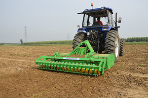
Inspection methods, procedures and precautions for rotary tillers
The rotary tiller is a drive-type tillage and soil preparation machine that is used in conjunction with a tractor.