

Inspection methods, procedures and precautions for the vehicle-mounted crane
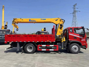
The truck crane integrates the "lifting" and "transportation" functions into a single device, which is capable of undertaking both loading and transportation tasks. Its inspection process differs from that of an automotive crane - not only does it need to verify the independent performance of the crane part, but also assess the structural coupling strength between the crane and the chassis, the operational stability of the crane in the loaded state, and the cumulative damage to the chassis beams and subframes caused by long-term "lifting and transportation" usage. The following examines the key inspection points from five dimensions: chassis subframe coupling, crane rotation and boom, hydraulic load, safety device interlock, and modification compliance.
1. Chassis and Subframe Coupling System - The Foundation of Load-bearing Capacity and Safety
The crane of the truck crane is installed on the chassis beam through the subframe (sub-rod), and this connection system's strength directly determines the stability and driving safety of the entire vehicle.
Subframe and main frame connection inspection
Connection method verification: U-shaped bolt connection is the mainstream method, while some use bolts directly. Check if the number and layout of the connection points are consistent with the modification plan - too few or improper positions will result in excessive concentrated load on the sub-rod, causing local stress exceeding the limit.
U-shaped bolt/Connection bolt torque: Use a torque wrench to randomly inspect each connection point according to the manufacturer's specified torque value, with no less than 30% of the total connection points. Any looseness indicates relative displacement between the sub-rod and the main rod.
Displacement trace inspection: Observe the paint surface of the contact area between the sub-rod and the main rod, for any frictional shine, paint peeling or rust powder - this is direct evidence of connection loosening and micro-movement wear. Any displacement traces must be expanded for inspection.
Packing wood/ Shock-absorbing blocks: There are usually wooden packing blocks or rubber shock-absorbing blocks between the sub-rod and the main rod to distribute the load and buffer vibration. Check if the packing blocks are intact, if they have shifted or cracked. If the packing blocks fall off, it will cause local direct contact between the sub-rod and the main rod, leading to stress concentration and cracking of the main rod.
Hidden areas of the main beam damage
Main beam area under the crane rotation base: This is the maximum bending moment point when the crane is fully loaded. Use a high-intensity flashlight to inspect the main beam flange and lower flange for any fine cracks - cracks often originate from the weld end or the edge of the bolt hole. This area is often obscured by the sub-rod and pipelines, making it a blind spot for inspection. Conditions must be created for observation or local disassembly is required.
Installation area of the rear legs: The rear legs bear the maximum reaction force during lifting, and the weld seam and bolt hole around the connection of the installation seat are high-risk areas for fatigue cracks.
Space coordination between the cargo box and the crane
Interference check in transportation state: After the crane boom is fully retracted and locked, check if the tail of the boom and the steel wire rope are hanging above the loading space of the cargo box. If there is interference, the loaded goods may collide with the crane boom or the steel wire rope, causing damage.
Interference check for cargo box lifting (for self-unloading truck cranes): If the chassis also has a self-unloading function, verify if the front of the vehicle will collide with the tail of the crane rotation when the cargo box is lifted to the maximum angle.
2. Crane Rotation and Boom System - Dual Core of Precision and Safety
Rotation bearing clearance quantitative measurement
Radial and axial clearance: Use a dial indicator seat to attach to the rotation platform or frame, with the dial head perpendicular to the outer edge of the rotation gear ring. In the fully extended state of the boom, apply horizontal force to the boom head manually and read the maximum deflection of the dial indicator as the radial clearance. Similarly, measure the axial clearance.
Judgment criteria: The clearance of the rotation bearing should be within the manufacturer's specified range. Excessive clearance will cause the boom to shake under load, not only affecting the lifting accuracy, but also indicating severe wear of the rolling elements/rolling surfaces of the rotation bearing, and there is a risk of fracture if it continues to be used.
Dynamic noise diagnosis during operation: Listen closely to the rotation bearing during the dynamic test. Periodic "clicking" sounds indicate pitting of the rolling surface or fragmentation of the rolling elements; continuous metallic friction sounds indicate the detachment of the sealing belt or dry lubricating grease.
Boom extension and sliding block wear
Measurement method: In the fully retracted state of the boom, use a feeler gauge to measure the up and down, left and right gaps between each section of the boom. The gaps should be uniform around the boom body, and uneven gaps on one side indicate excessive wear or missing of the slider on that side.
Slider condition: Observe through the inspection hole at the boom tail or the inspection port at the boom head, and visually check the wear degree of each telescopic slider/maintenance pad. If the slider is worn smooth or falls off, it will cause direct metal contact between the boom sections, leading to rapid wear of the boom and scratches.
Check of boom pin holes (single cylinder pin type): Open the boom tail maintenance cover, check whether the pin holes of each boom section are round and smooth, and whether there are any micro cracks at the edges. Elongated and deformed pin holes indicate that the pin once endured excessive shear force, and there is a risk of fracture.
Cumulative gap of folding boom hinge points
The folding boom has more than ten hinge points, and the small gaps between each pin shaft and the copper sleeve at each point will add up when the boom is fully extended, resulting in a significant shaking at the boom head. Use a feeler gauge to measure the gaps point by point, and record the over-limit hinge points. The integrity of the grease nipples and the state of grease overflow of all hinge points should also be checked.
III. Deep inspection of hydraulic system - Load capacity test
Rated pressure and relief pressure test
Install a pressure gauge group at the pressure measurement port of the hydraulic main pump outlet. At the rated engine speed, operate each working circuit (lateral movement, extension, lifting) to the extreme position, read the relief pressure, and compare it with the manufacturer's rated value. Insufficient relief pressure indicates wear of the main pump, malfunction of the relief valve, or system leakage.
Each circuit pressure should be tested one by one, and it is not sufficient to only measure the main relief pressure. If the pressure of a certain circuit is individually lower, it indicates leakage in the control valve or the actuator of that circuit.
Test of balance valve function for lateral movement cylinder
Raise the boom to approximately 60° of elevation, and return the handle to the neutral position. Hang the rated load or a load close to the rated value at the boom head. Observe if the boom has any obvious self-sliding within 5 minutes. Any visible self-sliding indicates leakage in the balance valve or the lateral movement cylinder, and it must be recorded and judged as unqualified.
The balance valve is a key safety element to prevent the boom from失控 and falling. Its failure is equivalent to the overall machine being unqualified in safety.
Test of hydraulic lock of each leg cylinder
Extend all the legs fully and support (lift the vehicle until the tires are about to leave the ground), and return the leg control valve to the neutral position. Wait for 10 minutes, and measure the extension change of the piston rods of each leg cylinder. Any obvious retraction of the cylinder indicates failure of the hydraulic lock, which will cause instability of the legs during the lifting process.
IV. Safety devices and electrical interlocks - The final line of defense
Measurement verification of torque limiter
Under the safe load, gradually increase the working amplitude (move the trolley forward or lower the boom laterally), verify the torque limiter to issue an audible and visual warning when reaching 90% of the rated load, and automatically cut off the dangerous direction actions (lifting, lateral movement lowering, outward extension of the boom) when reaching 100%-110%. Must witness the cutting action and record the actual load and amplitude at which it was triggered.
Failure of the torque limiter to be short-circuited or removed is a common human violation of the vehicle-mounted crane. During the inspection, check the integrity of the wiring harness of the torque limiter main unit, and look for any cut or jumper marks.
Leg status interlock
Simulate that one of the legs is not extended or not supported (retract the leg or hollow out the area under the leg), and operate the boom to rotate or lateral movement in the direction of that leg. The safety system should issue an alarm and limit the dangerous direction actions. Verify each working condition one by one.
Over-pull protection and three-circle protection
Slowly raise the hook close to the boom head, and over-pull protection should automatically cut off the lifting and issue an alarm within the specified distance. Lower the steel wire rope to the drum with no less than 3 turns of steel wire rope remaining, and over-release protection should trigger. Both must be measured.
V. Compliance of modification and special equipment review
The vehicle-mounted crane is largely in the form of adding a crane to the chassis, and the compliance of modification is the hard line for inspection.
Modification announcement and consistency Verify whether the combination of the crane model, rated lifting capacity, and chassis model is registered in the "Road Motor Vehicle Manufacturers and Products Announcement". Unauthorized modifications that are not announced are illegal and the vehicle will not pass the annual inspection. Driving on the road will face the risks of vehicle detention and fines.
Verify whether the actual vehicle's curb weight, overall dimensions, and announcement parameters are consistent.
Special Equipment Management Limits
Crane vehicles with a rated lifting capacity of ≥ 3 tons may be included in the management of special equipment (depending on the equipment type). It is necessary to verify the validity of the "Special Equipment Use Registration Certificate" and the "Periodic Inspection Report". If any documents are missing, they should be immediately recorded as a major management defect and a legal risk alert should be given to the client.
Six. Special Requirements for Inspection Safety
The area below and on the sides of the crane's working range is an absolute no-go zone. During load testing, no one is allowed to enter the area below the load and the dangerous fan-shaped area prone to overturning.
The ground on which the outriggers are supported must be solid. During soft ground testing, steel plates or road base boxes must be used to expand the grounding area of the outriggers.
During pressure inspection of the hydraulic system, it is strictly prohibited to directly touch the suspected leakage points with hands. Paper boards or leak detection sprays can be used instead.
Seven. Key Points for Taking Photos and Archiving
Close-up of the U-shaped bolts connecting the auxiliary beam and the main beam (including the condition of the wooden blocks).
Measurement process of the percentage gauge for the turning support (one for the radial direction and one for the axial direction).
Close-up of the wear of the slewing block/maintenance pad.
Photo of the reading on the torque limiter display at the moment of triggering.
Test process of the balance valve of the luffing cylinder under pressure retention (comparison of the crane's elevation angle at the beginning and end).
Test process of the hydraulic lock of the outrigger cylinder under pressure retention.
The combination of the crane nameplate and the chassis VIN code (used for verification of modification consistency).
Share this product
Inspection methods, procedures and precautions for the vehicle-mounted
The truck crane integrates the lifting and transportation functions into a single device, which is capable of undertaking both loading and transportation tasks.