

The inspection methods, procedures and precautions for bulldozers
The bulldozer is one of the machinery with the most severe working conditions and the greatest impact loads in earthwork engineering. The wear rate of its chassis traveling system, plow blade, loosening device and power transmission assembly far exceeds that of ordinary construction machinery. The core value of third-party inspection lies in converting the subjective experience of "still usable" into a quantitative judgment of "how long it can still be used" through instrumented measurement and standardized procedures. The following elaborates on the key inspection points from five dimensions: the main frame structure, four-wheel-and-one-axle chassis system, final drive, working device hydraulic system, and power transmission.
1. Depth Inspection of the Main Frame and Structural Components - The "Main Ribs" of the Bulldozer
The main frame of the bulldozer bears all the impact loads from the bulldozer blade, loosening device, and the traveling system. The structural integrity is the decisive factor for the safety and residual value of the equipment.
Detailed inspection of weld cracks on the main frame
High-stress zone identification: The areas prone to cracks in the main frame include - the welds of the pusher arm support/equalizer seat, the welds of the loosening device mounting seat, the connection point between the final drive housing and the frame, the support seats of the balance beam/wobble shaft, and the welding areas of the engine/transmission support beam.
Inspection method: Use a strong flashlight to approach the weld seam and shine it from multiple angles. Observe whether there are fine cracks along the weld seam direction on the paint surface (cracking of the paint surface is often an external signal of weld seam cracking), and check whether there are point-like rust stains at the weld seam edge (rust stains occur due to water seepage through cracks). Any suspected cracks must be ground off the paint layer and oxide scale using an angle grinder, and then perform PT (penetrant testing) or MT (magnetic particle testing) to confirm.
Evaluation of welding repair marks: Any welding repair area on the main frame must have a repair record traced. Unrecorded welding repairs must have their appearance quality evaluated - whether the weld seam is regular, if there are any undercutting, arc crater cracks, incomplete fusion, etc. Are there any new cracks extending around the welding repair area? Welding repairs without welding process records and with poor appearance quality should be judged as serious defects.
Hidden damage to the final drive housing
The final drive housing not only bears the internal gear meshing force but also withstands the external impact from the tracks. Check the torque of the connecting bolts between the housing and the frame, and inspect for any cracks on the housing surface - especially around the bolt holes and at the roots of the reinforcing ribs.
The gear oil condition inside the final drive housing - drain the oil and inspect the color of the oil and metal debris. Silver-gray metal particles indicate abnormal wear of the bearings or gears, while copper-colored powder indicates wear of the copper sleeve or cage.
The concealed clearance between the balance beam and the swing shaft
If the balance beam pin and bushing wear excessively, it will cause abnormal shaking of the frame during the crawler movement, accelerating the fatigue of the entire chassis system. Use a feeler gauge or micrometer to measure the gap of the pin, and if it exceeds the manufacturer's limit, it should be recorded as a repair item.
Verification of swing shaft function - When driving on uneven terrain, the balance beam should be able to swing freely to adapt to the terrain. Stuck swing will result in uneven traction of the tracks and additional stress on the structure.
II. In-depth Inspection of the Four-Wheel and Belt Chassis System - The Dual Core of Value and Safety
The cost of replacing the entire chassis assembly of the crawler行走 system may account for a significant proportion of the total machine value, and it is the most crucial reference basis for valuing second-hand bulldozers.
Precise measurement of the link rail spacing
Measurement method: When the tracks are tightened, use a caliper or a special chain gauge to measure the length of 4 to 5 chain link sections. Divide the total length by the number of sections to obtain the average pitch. At least 3 measurement points should be taken on each of the left and right tracks.
Judgment criteria: When the distance between the chain links exceeds the original factory standard value by 2% to 3%, the meshing between the chain links and the driving wheel teeth will deteriorate, accelerating the wear of the driving wheel. If the stretching exceeds the standard and there are obvious wear steps on the chain link pins/sleeves, it is recommended to replace the chain links and the driving wheels as a set.
Wear classification of the driving wheels
Normal wear and tear - The tooth surface becomes a smooth curved surface, and the tooth thickness gradually thins out evenly.
Abnormal wear characteristics and causes:
Sharpening of tooth tips (hook-shaped wear): The pitch of the chain track is stretched too much, resulting in a single-point contact between the chain links and the tooth tips.
Pitting or tooth breakage on the gear surface: Excessive impact load or material defect.
A step appears at the tooth root: The chain track is overstretched, and the sleeve slides and rubs against the tooth root.
Measure the tooth thickness using a caliper or a dedicated tooth profile template, and compare it with the manufacturer's wear limit value.
Detection of the support wheel and the idler wheel
Rotate each wheel and check for any jamming or uneven wear marks. If the floating oil seal is leaking, oil can be seen seeping out from the surface, and the internal lubricating oil has leaked out. The bearings and shaft sleeves will fail to function properly in the short term due to lack of lubrication.
The wear depth of the contact surface between the support wheel body and the chain track is measured using a caliper. If the wear is too deep, it will affect the track guidance and the stability of the walking.
Dynamic adjustment of the tension of the tracks
Use a ruler and a tape measure to measure the deflection of the upper sprocket between the two sprocket wheels, and compare it with the manufacturer's standard value. If it is too loose, it will cause derailment and teeth jumping of the driving wheel, and if it is too tight, it will sharply increase the wear of the chain track pin sleeve and the load on the final drive bearing.
Tightening of the grease cylinder function - The oil injection nozzle is in good condition, the cylinder body has no leakage, and the tension stroke margin is sufficient. For the tension cylinder whose stroke has been exhausted, even if the current tension is appropriate, it still indicates that the chain track has been over-stretched and needs to be replaced soon.
III. In-depth Inspection of Power Transmission System
Hydraulic Torque Converter and Transmission Gearbox
Transmission oil level and quality - Use an oil dipstick to check the oil level and observe the color of the oil. Dark brown and black with a burnt smell indicates abnormal wear of the clutch plates or long-term high-temperature oxidation of the oil. Metal suspended particles indicate damage to gears or bearings.
Stall test (if possible): On a safe area, simultaneously press the brake pedal and accelerator pedal. The engine speed should remain stable at the stall speed specified by the manufacturer. A low stall speed indicates insufficient engine power, while a high stall speed suggests failure of the torque converter drive wheel one-way clutch or slipping of the transmission clutch.
Shift smoothness - Each gear position allows for forward and reverse transitions. The shift operation should be smooth without any jolts, slipping, or abnormal noises. Shift delays or shock indications may indicate clutch wear or hydraulic control valve failure.
Steering clutch and brake
The wet multi-disc steering clutch/brake cannot be directly observed inside the housing. It is mainly determined through dynamic testing.
Level test: Pull the left and right steering levers respectively. The bulldozer should be able to smoothly turn around on one side of its tracks. If there is insufficient steering force, failure of single-side steering, or sharp noises during steering, it indicates that the friction plate of the steering clutch on that side is worn out, the hydraulic pressure is insufficient, or the brake band has failed.
Grade parking brake: Tighten the parking brake on a safe slope. The excavator should be securely parked without any sliding. If the parking brake fails, it must be repaired immediately.
IV. In-depth Inspection of Working Devices and Hydraulic System
Quantification of Wear on Bulldozer Blades and Tilling Devices
The bottom of the shovel is measured using an ultrasonic thickness gauge with grid points. The minimum wall thickness is recorded and compared with the original specification. When the wall thickness is reduced by more than 30%, the impact resistance of the shovel has significantly decreased.
Shovel blade/blade - The remaining edge height is measured using a caliper. The fixing bolts of the blade are inspected one by one for any signs of loosening or fracture.
Connect the push arm and the shovel blade pin shaft and bushing - Use a feeler gauge to measure the gap. An excessively large gap will result in decreased control accuracy of the shovel blade and elliptical deformation of the pin hole.
Hydraulic system pressure and pressure retention test
A hydraulic pressure measuring device group is installed at the pressure measurement port of the main pump to measure the overflow pressure of the working device circuit at the rated speed, and compare it with the manufacturer's standard. If the overflow pressure is insufficient, it indicates that the main pump is worn or the overflow valve is out of adjustment.
Pneumatic shovel lifting cylinder pressure retention test - Raise the shovel to the highest position, turn off the engine, mark the position of the cylinder piston rod, and leave it for 10 minutes. If the piston rod sinks more than the standard (usually 10 minutes ≤ 15mm), it indicates internal leakage in the cylinder or leakage at the reversing valve.
Pilot control system
The operation feel of the pilot control handle - it should be neither too heavy nor too light, and the return should be accurate. Insufficient pressure in the pilot oil circuit will result in heavy operation and sluggish response.
V. Special Inspection Points
Cab ROPS/FOPS Structure
The anti-rollover/anti-falling object protection structure is a mandatory safety feature for mining operation bulldozers. The cab pillars have no bending or deformation, the top is without dents, and the welding areas have no cracks. Any structural damage must be deemed as non-compliant.
Centralized lubrication system (if equipped)
The grease pump is operating normally, and grease is being discharged from each outlet of the distributor. The grease leakage status at each hinge point of the bulldozer blade, soil loosener, and balance beam - dry hinge points indicate that the distributor is clogged or the pipeline is damaged.
Oil analysis - The gold standard for in-depth diagnosis
The maintenance costs for the transmission system and final drive of the bulldozer are very high. It is strongly recommended to collect samples of engine oil, transmission oil, hydraulic oil, and final drive gear oil and send them to the laboratory for elemental spectroscopy analysis.
Abnormally elevated iron and copper elements in the transmission oil indicate wear of gears/bearings or abnormal wear of clutch plates; an increase in silicon content in the hydraulic oil suggests aging of seals or intrusion of external dust.
The security boundaries of dynamic testing
The trowels and loosening devices of the bulldozer have a wide movement range. During dynamic testing, no one is allowed to stand around.
When the crawler makes a turn on the spot, it may throw off rock fragments. Observers must maintain a safe distance.
When conducting the slope test for steering and braking, it is necessary to formulate contingency plans for preventing vehicle skidding and make preparations for emergency rescue.
Key points for photo archives
The PIN code and the entire machine's nameplate are independently archived.
The process of measuring the pitch of the chain link (the reading displayed by the caliper is in the same frame as the measurement section).
Close-up of drive gear surface wear (from multiple angles).
The thickness measurement reading of the bottom of the shovel is displayed in the same frame as the measurement location.
The weld condition of the push arm support of the main frame (if there is an inspection result, please attach an image of the inspection result).
Photo showing the labels of the oil sample bottles corresponding to the sampling locations.
Share this product
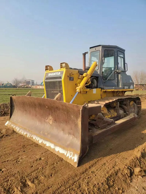
The inspection methods, procedures and precautions for bulldozers
The bulldozer is one of the machines with the most severe working conditions and the greatest impact loads in earthwork and excavation projects.